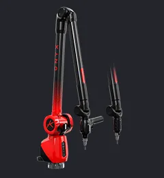
Product menu measuring arm Onyx with 3d scanner SkylineOnyx menuMenu - Onyx measuring arm with 3D scannerProduct menu measuring arm Ace with 3d scanner SkylineProduct menu Skyline 3D scannerProduct menu Zephyr III 3D scannerProduct menu Track AceProduct menu scanning robotProduct menu CMM scanningProduct menu Zenith metrology softwarePlugin menu
Measuring arms
OnyxAce
Measuring arms
with 3D scanners
Onyx SkylineAce Skyline
3D scanners
SkylineZephyr III
Scanning solutions
Scanning CMMsTrack Ace

CAD comparison

The comparison of CAD (Computer-Aided Design) model through color mapping is a technique used in the field of inspection and quality control to evaluate the conformity of an existing part .

Here is how the CAD comparison process through color mapping usually works:

Data acquisition

A 3D scanner is used to capture the geometry of the existing part by performing a complete or partial scan of its surface. The 3D scanner collects spatial information in the form of a point cloud or mesh representing the surface of the part.

CAD model import

The reference CAD model is imported into the inspection software. This model represents the theoretical geometry and specified dimensions of the part.

Data alignment

The data captured by the 3D scanner is aligned with the CAD model to ensure accurate correspondence between the existing part and the virtual model.

Data comparison

The software compares the point cloud data with the information from the CAD model by using matching and deviation detection algorithms.

Color mapping

Deviations between the existing part and the CAD model are visualized by using color mapping. Different colors are assigned to different areas of the part based on the magnitude and direction of the deviations. For example, conforming areas appear in green, while non-conforming areas may appear in red or blue.

Deviation analysis

The results of the CAD comparison through color mapping are used to identify specific areas of the part that do not conform to the CAD model. Operators can visually analyze the deviations and decide for any necessary adjustments or corrective measures.
Deviation analysis
Alignment of the scanning data with the CAD file
Import CAD
Scanning an engine with Ace measuring arm

By using CAD comparison through color mapping, it becomes easier and faster to evaluate the conformity of an existing part with the CAD model because deviations are visualized clearly and intuitively. This facilitates the identification of non-conformities and helps make informed decisions to improve the quality of the produced parts.

Why use a measurement arm with Kreon 3D scanner for part inspection through CAD comparison?

One of our customers bought a measuring arm for CAD comparison. Take a look and see how he uses it!

Discover the Case study
Using the Ace Measuring Arm on Carbon Fiber Parts