Measuring arms
OnyxAceMeasuring arms
with 3D scanners
Onyx SkylineAce Skylinewith 3D scanners


Geometric Dimensioning and Tolerancing (GD&T) is a symbolic language, crucial for describing the geometric characteristics, and tolerances on a part and assemblies. It provides standardized symbolic language to the designers, manufacturers, and inspectors to convey the necessary information in the designing and manufacturing process. This helps to prevent mistakes during the design and manufacturing process.

GD&T ensures clear communication by using technical terminology for geometric characteristics such as flatness, concentricity, cylindricity, shape profile, true position, and runout despite country location and language.
This language is encoded in symbols and annotations indicating some specific rules- defining its geometric tolerances, references,and the relationship between features to ensure the manufactured part meets the desired specifications.
It helps to make sure that the different parts of a product are shaped and positioned relative to each other, and that they fit together correctly to perform their intended functions. This improves the consistency and quality of manufactured products.

GD&T's Geometric Dimensioning involves explicitly stating and controlling the geometric dimensions of a part's features. It clearly illustrates the geometric elements (plane, circle, line, etc.) on a specific zone relative to a particular part.
Tolerancing in GD&T means setting limits on how much a part's dimensions and characteristics can vary. It makes sure that the part will function correctly corresponding with the relative parts and within its tolerance zone specified by GD&T.

GD&T uses symbols and notations to define the shape, size, and tolerances of a part, creating a manufacturing blueprint. In the past, information was typically conveyed using 2D technical drawings.Nowadays, modern GD&T software can also integrate this information directly into the 3D CAD model (Computer-Aided Design).
For each feature, it then creates a control frame containing all information such as symbol, tolerance, and datums like planes,cylinders, and circles to ensure consistent measurement references.
After manufacturing the parts, and to ensure compliance of the entities with GD&T specifications, precise quality control must be carried out. The process then employs measuring arms, Coordinates Measuring Machines (CMMs), 3D Scanners and other metrology tools.
The data collected is compared with the CAD model to check for differences in the manufactured part. The tolerances are also used in this comparison. To confirm if the inspected features are within acceptable limits. All inspected data including the 3D scans and reports are documented for traceability and future reference to understand the manufacturing process,identify trends, and improve the overall quality.

Let’s say you have a metal plate with a specified flatness tolerance of 1.00 mm. If the flatness is called out on a drawing using GD&T, it might be represented as follows:
Flatness: 1.00 mm
This means that the entire surface of the metal plate must not deviate from a true flat plane by more than 1.00 mm. Inspectors would use measurement tools such as surface plates, straightedges, or specialized equipment to check and verify that the actual surface conforms to the specified flatness tolerance. If the measured deviations exceed the tolerance, it would be considered non-conforming.

Technological and manufacturing advancements in engineering patterns and designs are evolving into complex and sophisticated structures. To describe these mechanical structures, the machinist requires the most precise and trustable method of communication. GD&T saves time,reduces costs, and improves productivity.
Manufacturing a complex part demands a great effort from the initial stages of designing. The more composite the design of the product gets, the more compact the tolerances are. If the specifications of the parts are conveyed appropriately in the process it can avoid the scrappages. Hence, it requires high-level metrological tools such as 3D scanners, measuring arms, and CMMs for quality control and inspection. These tools help to meet the quality control requirements of any project and in any circumstances.

Engaging in Geometric Dimensioning and Tolerancing (GD&T) inspections presents certain challenges, with some issues being the potential for misinterpretation. Despite the clarity in annotations and definitions, designers and inspectors need thorough training to correctly use and understand GD&T principles.
Two primary sets of standards presently govern Geometric Dimensioning and Tolerancing (GD&T). The Geometrical Product Specifications, referred to as ISO GPS Standards, is a collection of standards published by the International Organization for Standardization (ISO).Concurrently, the American Society of Mechanical Engineers (ASME) issues the ASME Y14.5 Standard, shaping the landscape of GD&T standards in the United States.

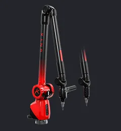
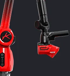
Kreon's measuring arms offer unparalleled flexibility, allowing inspections to be carried out in diverse setups, whether in workshop environments, measuring laboratories, or even outdoor facilities. These versatile arms maintain exceptional measurement quality while ensuring portability and ease of use. Particularly, the Onyx arm stands out for its precision, enabling inspection of parts through probing to verify tolerances stipulated by GD&T, thereby ensuring that components meet the right specifications.
Skyline 3D Scanners work smoothly with measuring arms to quickly scan any intricate part, regardless of its size, shape, or material.
Kreon’s High-performance Skyline range of 3D scanners are tailored for all kinds of applications in any industry such as Automobile and Aerospace. Depending on the model, Skyline’s proficiency in scanning intricate parts with laser width up to 200 mm, lightning-fast speed at 600,000pts/sec and accuracy up to 9 μm is crucial for precise measurements. It enhances quality control, where manufacturing variations can have significant implications on product performance and compliance.
Kreon’s most accurate scanning range of 3D scanner Zephyr III delivers an unrivalled accuracy of up to 5 µm to capture meticulous details with a scanning speed of 600,000 pts/sec. Zephyr III also delivering high acquisition frequency with a wide laser line up to 300 mm to meet rapidly growing productivity needs in the industry.
Embedding more than 30 years of expertise in 3D Scanning, Zephyr III 3DScanners set a standard of the high level of scanning technology making it possible to perform numerous operations such as GD&T analyses and color mapping, with complete confidence.
The Zephyr III 3D Scanners are automated and integrated into CMM. They can scan in multi-oriented positions, constantly improving the control time while controlling the full part. Moreover, with CMM integration, Zephyr III streamlines the inspection process, improves efficiency, and ensures accurate GD&T assessments.
Zephyr III scanners are not limited to a specific platform; they can be used with robots, portable CMMs, and CNC machines.
The integration of probes under the scanners is a patented solution by Kreon. This innovation enables seamless scanning and probing within the same measurement range, eliminating the need for disassembly, and saving valuable time. This unique combination enhances versatility, allowing for precise probing of geometric entities, such as verifying GD&T specifications, and swift scanning of entire part to detect surface deformations or defects.
From automotive to aerospace, these advanced metrology tools empower manufacturers to deliver superior products that meet customer expectations and regulatory requirements.
Kreon’s commitment to performance and innovation provides Zenith, a software designed for Kreon measuring arms and easily manageable for scanning and probing any industrial parts for quality control. Zenith's extended capabilities not only provide fast point cloud acquisition but also deliver a CAD comparison through extraction from CAD and color mapping.
GD&T system is incorporated within the Zenith software making it well-suited for demanding parts. Zenith is configured to handle key GD&T aspects such as form tolerances (flatness, cylindricity, circularity), orientation tolerances (perpendicularity, parallelism,angularity), and position tolerances (coaxility, concentricity). Moreover, Zenith’s advanced sectioning functions allow users to create sections of both nominal and measured parts, enabling distance analysis and angles, for in-depth GD&T tests.

In conclusion, Kreon’s measuring arms, 3D scanners, and software solutions emerge as indispensable assets in the realm of GD&T verification and quality control. By seamlessly integrating advanced technology with precision engineering, Kreon empowers manufacturers to uphold rigorous GD&T standards, enhance productivity, and deliver products of exceptional quality across various industry sectors.


